Ubiquitous Computing [25] envisions physical spaces, such as offices or homes that are augmented with computing devices integrated into the environment. It aims to make services provided by these devices as commonly available to end-users as electricity. It corresponds to the next generation of computing in which the user’s attention will not be drawn to computers but vice versa, i.e. computers will be attentive to user interactions and aid their daily activities.
Sentient Computing [6][1] is our approach to making Ubiquitous Computing a reality. It creates perceptive living spaces [2] where users activities are enhanced by software services provided by devices embedded in the environment. These environments achieve awareness of their surroundings through sensors that capture contextual information such as the location and identity of objects or the ambient sound level and temperature of a physical space. Sentient Computing combines the dynamic information conveyed by sensors with static information from data repositories (e.g. entity attributes, the geometric features of a physical location or the capabilities of devices) in order to build a model of the environment’s state. Assisted by such model, sentient systems aim to perform the right service at the right time on behalf of users. In essence, computers are given perception so that they can become reactive to the people and activities taking place around them.
Location-aware Computing [23], whose behaviour is determined by the position of objects in the environment, represents an interesting subset of the Sentient Computing paradigm. The location attribute of context can be used to convert the space users inhabit into a global interface with computers [4], rather than limiting users to the classical desktop-bound interaction. In the last few years, several custom-built indoor location systems have appeared providing different entity location granularity. The location information provided ranges from room-scale resolution such as the infrared-based Active Badge [23], to more accurate 3-D coordinate resolution offered by systems such as the ultrasound-based Active Bat [24] or the radio-based 3-D-iD [27]. Most of these indoor location systems require people and objects to be located to wear an electronic tag that transmits a unique identifier via either an infrared, ultrasound or radio interface to a network of sensors on the walls or ceilings of a building. A Location Server polls and analyses the information from the sensors and makes it available to applications.
Despite their proved usability, most of existing indoor location systems [5] have some important drawbacks. The tags they use are proprietary and need battery power to operate. The infrastructure required, i.e. a network of sensors, is complex and expensive to install and maintain. The cost of these networks of sensors is usually around $1,000-2,000 per room. These factors have limited the deployment of such positioning systems to research laboratories. We have devised an alternative sensor technology, known as TRIP that is deemed to provide a better trade-off between the price and flexibility and the accuracy of the location data provided. In what follows, a detailed overview is given of the TRIP technology and its main areas of application.
2. A Vision-Based Location Sensor
TRIP (Target Recognition using Image Processing) is a vision-based sensor system that uses a combination of 2-D circular barcode tags or ringcodes (see Fig. 1), and inexpensive CCD cameras (e.g. web-cams or CCTV cameras) to identify and locate tagged objects in the cameras’ field of view. Compared with untagged vision-based location systems [8][19], the processing demands of TRIP are low. Optimised image processing and computer vision algorithms are applied to obtain, in real-time, the identifier (TRIPcode) and pose (location and orientation) of a target with respect to the viewing camera.
Fig. 1. TRIPcode of radius 58mm and ID 18,795.
TRIP is an cost-efficient and versatile sensor technology. Only low-cost (e.g. web-cams below $50), low-resolution (640x480 pixel) cameras are required. The spare computing resources within a LAN can be allocated to run the TRIP image parsing software, without the need of investing in new PCs. Commonly available monochromatic printers can be used to print out the black and white TRIPtags. The off-the-shelf hardware requirements and software nature of TRIP make possible its installation in offices, or event at homes, equipped with some PCs, without requiring significant additional costs or expert technical knowledge. A medium size (4x4 m2) room could be visually covered with three or four cameras.
TRIP’s 2-D printable and resizable ringcodes (TRIPtags) encode a ternary number in the range 1-19,683(39 - 1) in the two concentric rings surrounding the bull’s-eye of a target. These two rings are divided into 16 sectors. The first sector or synchronisation sector indicates where the TRIPcode begins. This sector presents black areas in its section of the encoding rings, a configuration impossible everywhere else in the code. The code is read in anti-clockwise fashion from this sector. The subsequent two sectors are reserved for undertaking an even parity check on the identifier (TRIPcode) extracted. The following four sectors encode the radius of its central bull’s-eye in millimetres. Finally, the remaining nine sectors encode a ternary identifier.
The low-cost of TRIPtags and their ample addressing space (19,683 possible codes) make them suitable for tagging even low-cost items, such as books or office stationary. In contrast, other location sensing technologies can only tag more valuable assets, e.g. personnel or equipment, given the high cost (usually $10-50) and thickness (1-2 cm) of the associated tags. Notably, the main constraint of TRIP is its requirement for a direct line of sight between the camera and the tag. However, we believe the advantageous features of this technology over other alternative location technologies offset this important drawback.. The ultimate goal of this project is to provide a downloadable version of the system so that users with web-cams attached to their PCs may install the TRIP software and hence provide visual awareness to their machines.
2.1. Target Design Criteria
Conventionally, researchers have used visual cues (markers) of known geometric properties to facilitate the identification and localization of objects in the field of view of video cameras. Markers of known size and shape can yield a wealth of geometric information when transformed under the perspective projection. In particular, circular [20] and square [7][16] markers have been utilised to extract the accurate position and orientation of tagged objects. These markers permit the application of simple and fast-performing image processing and computer vision algorithms to the difficult task of obtaining 3-D position from a 2-D image.
Our marker (see Fig. 1) is based on a circular pattern since circles are less ambiguous than squares for their identification and 3-D localization using a visual sensor. In man-made environments, circles are less common shapes than right angles, squares and rectangles. TRIP is intended for the localization of tagged objects in these highly cluttered environments (see Fig. 2), where the central bull’s-eye of a TRIPtag represents a very distinctive pattern. The detection of squares in those cluttered environment supposes an expensive computational task given the many straight edges combinations possible within an image. An even more unusual shape could have been chosen, e.g. a star. In this case, however, there is the problem of representing such a shape in a compact way and to encode useful information (e.g. ID) around or within it. A circle, and its projection in an image as an ellipse, can be represented in a compact and elegant form by a symmetric (3x3) matrix. Moreover, ellipses in an image are salient features and can be detected robustly and rapidly by methods such as [15].
A second important aspect in the design of a marker, apart from its shape, is the set of colours used in order to provide a distinctive contrast between the marker and the surrounding objects. TRIP targets were chosen to be black and white patterns since: (1) it is computationally cheaper to process monochromatic images rather than colour ones, and (2) monochromatic printers are also more widely available than colour ones. Using colour is both difficult and unreliable since the lighting conditions can change too much and the colour sensitivity of various CCD devices are very different.
2.2. TRIP Target Recognition
TRIP applies a target recognition algorithm to the raw video data supplied by a camera in order to determine the identifiers and geometric properties of the projections of TRIPtags in a frame. This procedure converts the TRIP system into an entity identification sensor. Fig. 2 depicts the video filtering process undertaken to an image containing a TRIPtag. The set of image processing stages applied to each greyscale image grabbed are:
1. The original image is transformed into a binary image with increased contrast level by applying an adaptive thresholding procedure [26]. This stage makes TRIP’s image analysis very robust to variable lighting conditions and suitable even for low-cost, low-quality CCTV or web-cams.
2.
One-pixel width edges in the binary image are extracted by
applying a very computationally efficient binary edge detection method. This
method applies the following criteria to a binary image: “A pixel is an edge
point if it has black intensity value and an adjacent (4-connected) neighbour
pixel with white intensity value and a diagonally adjacent (8-connected) one
with black intensity value”.
3. All the 8-connected chains of edge points (edgel) are followed in a clockwise fashion, producing for each edge a list of ordered point locations. TRIP is only concerned with edges corresponding to the perspective projections of the circular borders of TRIPtags, i.e. ellipses. Thus, only edges whose shape is likely to define an elliptical shape are kept. For this, a simple heuristic is applied that analyses the ratio between the Euclidean distance of the extremes of an edge and its length in pixels.
4. The direct least-squares ellipse fitting method developed by Pilu et al. [15] is applied to each elliptical edge candidate encountered, obtaining the ellipse parameters that best approximate the edge points.
5. The ellipses found are tested for concentricity in order to identify candidate TRIPcodes.
6. The code deciphering stage is undertaken. This method applies an efficient pixel-sampling mechanism on the binary image result of stage 1, based on the parameters of the outermost ellipse of a candidate TRIPcode. The ternary codes obtained are validated against the two even parity check bits reserved in a TRIPcode.
7. For each TRIPtag spotted within an image TRIP returns: (a) the ternary identifier, (b) the parameters of the implicit equation of the outermost elliptical border of the projection of target, (c) the radius of the target and (d) the image location of the bottom outermost corner of the synchronisation sector of a TRIPtag (this point is identified during stage 6).
2.3. TRIP Target Pose Extraction
The TRIP sensor system applies a model-based object location technique [21] to a single intensity image in order to extract the pose of TRIP-tagged objects with respect to a viewing camera. The ‘TRIPtag object model’ (see Fig. 3) is composed of: (1) the outermost circular border of the central bull’s-eye and (2) a point outside the bull’s-eye (denoted by P in), lying on the X-axis of the target centred coordinate system. This point corresponds to the bottom outermost corner of the synchronisation sector of a TRIPtag.
Fig. 3. TRIPtag geometric model.
The model-based object location technique used, namely POSE_FROM_TRIPTAG, takes as input the outcome of the target recognition process in order to determine the accurate 3-D location and orientation of identified TRIPtags with respect to the viewing cameras. This method establishes a transformation that back-projects the elliptical projection of the outermost border of a target into its actual circular form, of known radius, in the target plane. The radius of the outermost border of a target’s bull’s-eye is encoded within the 4 ternary bits reserved for this purpose in a TRIPcode. In addition, the image location of the bottom outermost corner of the synchronisation sector of a TRIPtag is necessary. This point is situated on the X-axis of the target centred coordinate system.
The POSE_FROM_TRIPTAG method returns the translation vector [Tx Ty Tz] and rotation angles (a, b, g) that define the rigid body transformation between a camera coordinate system and a target centred coordinate system. The bottom right hand side of Fig. 2 shows the results of applying such process to an image. This method exploits the property unique to a conic that is a circle that the back-projected curve’s implicit equation must have equal coefficients x2 and y2 and no term in xy. The algorithm was inspired by the POSE_FROM_CIRCLE method described in [3].
The geometry applied by the POSE_FROM_TRIPTAG method is shown in Fig. 4 and Fig. 5. The ellipse corresponding to
the image of the outermost circular border of the bull’s-eye of a target
defines a cone with its vertex at the centre of projection of the pinhole
camera (O). The orientation of the target’s plane, Pt, is found by rotating
the camera so that the intersection of the cone with the image plane becomes a
circle, which happens when the image plane, Pi, is parallel to the
target plane, Pt. This rotation can be
estimated as the composition of two successive rotations. The first, see Fig.
4, is a 3D rotation that puts the Z axis through the centre of the
target, and aligns the X and Y axes with the axes of the image
ellipse; the second, see Fig. 5, rotates the newly found coordinate system
around Y’ until the image plane becomes parallel to Pt.

Fig. 4. 3D rotation of (X,Y,Z)
to the eigenvector frame (X', Y¢, Z¢).

Fig. 5. Rotation of plane Pi about the Y' axis by an angle θ.
TRIP makes the assumption that the intrinsic parameters of the camera are known. In other words, the user is required to undertake the well-known camera calibration [22] process once for each CCD camera. Fortunately, there are several publicly available software packages for camera calibration, e.g. [22][28]. The following sub-sections explain thoroughly the projective geometry used to find the pose of a TRIPtag in the scene.
2.3.1. Target Pane Orientation
The POSE_FROM_TRIPTAG method assumes that the ellipse in the image taken as reference is expressed in the camera coordinate system rather than in the image plane pixel coordinates as returned by the target recognition process. Consequently, the ellipse, C, is normalised by using the matrix, K, of the camera intrinsic parameters (see Eq. 1). The intrinsic parameters of a camera are defined as the focal length, f, the intersection of the optical axis (Z-axis in Fig. 4) with the image plane (u0, v0), the effective pixel size in the horizontal and vertical direction (ku, kv), and the pixel skew ka. For most CCD cameras the pixels are almost perfectly rectangular and thus ka»0. Note that the superscript T in Eq. 1 stands for transpose.

The normalized ellipse, Cn, corresponding to the projection of the outermost circular border of a target’s bull’s-eye, defines a cone with vertex in the centre of projection of the pinhole camera, denoted by O (see Fig. 4). Let ax2+bxy+cy2+dx+ey+f = 0 be the equation of this normalized ellipse, then there is a cone in 3-D defined as:
ax2+bxy+cy2+dxz+eyz+fz2
= PTCnP = 0 Eq. 2
where P=[X Y Z]T is a point in the cone and Cn is the real symmetric matrix of a cone:
 Eq.
3
Eq.
3
The orientation of the circle’s plane, Pt, is found by rotating the camera so that the intersection of the cone with the image plane becomes a circle, which happens when the image plane, Pi, is parallel to the target plane. This rotation is estimated as the composition of two successive rotations, namely R1 and R2:
![]() Eq. 4
Eq. 4
The first rotation, R1, is
determined by diagonalising Cn,
i.e. removing the coefficients with
terms in xy, xz
and yz. This 3-D rotation (see Fig. 4)
transforms the camera coordinate system, OXYZ, to the eigenvector frame,
OX’Y’Z’, and the ellipse matrix Cn
into C’. If l1, l2, l3 are the eigenvalues of Cn, with l1 < l2 < l3 and ![]() ,
, ![]() ,
, ![]() , the corresponding eigenvectors, then:
, the corresponding eigenvectors, then:
![]()
![]()
 Eq. 5
Eq. 5
The second rotation, R2, is obtained by imposing the equality of the coefficients of x2 and y2 in C¢. R2 represents a rotation around the Y’ axis by an angle q, as shown in Eq. 6. This rotation, R2, sends a point P’ to P’’ and transforms C’ into C¢¢ (see Fig. 5):
![]()
![]()
![]()
The composite rotation RC,
result of multiplying R1 and R2,
makes the image plane parallel to the target plane (see Fig. 5). Consequently a
vector normal to the target plane can be obtained by applying Eq. 7. Vector ![]() represents the
orientation of the plane Pt expressed in the camera
coordinate system.
represents the
orientation of the plane Pt expressed in the camera
coordinate system.
As result of Eq. 6, there is a two-fold ambiguity in the recovered
orientation, depending on which sign of q is chosen, i.e. ![]() from RC1
and
from RC1
and ![]() from RC2.
Section 2.3.3. explains the
geometric interpretation of this result and a procedure to break this
ambiguity.
from RC2.
Section 2.3.3. explains the
geometric interpretation of this result and a procedure to break this
ambiguity.
2.3.2. Target 3-D Location
C¢¢ represents a circle in the rotated image plane (Pr) of radius r0 and centre (x0, 0, 1), in terms of the coordinate system OX¢¢Y¢¢Z¢¢ (see Figure 4):

If
correspondences are established between the expressions for C¢¢ in Eq. 6 and Eq. 8, then the following expressions can be obtained to
calculate x0 and r0.

Fig. 6. Geometric relations between planes Pr and Pt.
The distance between the camera and the target plane, denoted by d, can be obtained by applying triangle similarity principles to the triangle couples OOcA-Oocx0 and OOcB-Oocr0 shown in Fig. 6. From triangles OOcA and Oocx0 it can be inferred:
From triangles OOcB and Oocr0, and applying Eq. 9 and Eq. 10, an expression for δ in terms of the eigenvalues of Cn and the known radius of the outermost border of a target’s bull’s-eye, r, can be derived (see Eq. 11). Similarly, substituting Eq. 11 in Eq. 10, an expression for the distance of the target plane to the camera origin, d, is obtained (see Eq. 12):
The 3-D coordinates of the centre of the
target (see Fig. 5) are given by the translation vector, ![]() , expressed in the OX¢¢Y¢¢Z¢¢ frame.
, expressed in the OX¢¢Y¢¢Z¢¢ frame. ![]() can be calculated in
terms of the original coordinate system OXYZ as:
can be calculated in
terms of the original coordinate system OXYZ as:
![]() Eq.
13
Eq.
13
Again, as a consequence of equation Eq. 6, there are two possible solutions for the translation
vector, i.e. ![]() and
and ![]() .
.
2.3.3. Breaking the ambiguity
As noted by the previous two sections, the POSE_FROM_TRIPTAG method returns two possible pose solutions. This result can be explained geometrically by observing Fig. 7. Circle 1 and circle 2, lying on planes P1 and P2, respectively, and with the same radius r are projected to the same ellipse in the image plane. Consequently, it is necessary to use additional information, apart from the ellipse of reference, in order to be able of deciding which of the two solutions is the real one. For TRIP, this additional information is provided by the known projection of the bottom outermost corner of the synchronisation sector of a TRIPtag (see Fig. 1). The projection of this point is accurately identified by the code deciphering stage of the target recognition process, described in section 2.2. Likewise, the location of this point in the target centred coordinate system is also known (see Fig. 3). If the projections of this point, obtained by means of the two rigid body transformations returned by the POSE_FROM_TRIPTAG method, are compared with the known projection of this point in the image, the right solution can be determined. The point projection lying closest to the known projection in the image will correspond to the right solution. Fig. 8 shows how the projection of a point at a distance r+d from the centre of a circle in plane P1 will differ significantly from the projection of the same point lying on plane P2.
The projection of point P=[2.2×r 0 0 1]T (expressed in homogenous coordinates) in the TRIPtag plane into point p=[su sv s]T in the image plane can be obtained by applying the planar projective transformation [21]:

The planar
projective transformation exploits the fact that every point lying on the
target plane has a value of Z=0. Eq. 14 can be applied to the two feasible results obtained, i.e.
(RC1 and ![]() ) and (RC2 and
) and (RC2 and ![]() ), so as to calculate the projections p1
and p2. In order to measure the distances between p1
and p (the known projection of the point in the image), and p2 and
p, the homogeneous coordinates of these points are transformed into
Cartesian coordinates. The right
solution should project P into a point lying very close to p:
), so as to calculate the projections p1
and p2. In order to measure the distances between p1
and p (the known projection of the point in the image), and p2 and
p, the homogeneous coordinates of these points are transformed into
Cartesian coordinates. The right
solution should project P into a point lying very close to p:

Eq. 15

Fig. 7. Circle projection ambiguity.

Fig. 8. Projections of points P1
and P2 at r+d distance from C1
and C2.
2.3.4. Target’s Rotation Angles
The use of a circle as a reference has provided a closed form solution to the determination of the 3-D pose of a TRIPtag. Unfortunately, the view of a planar circle, due to its symmetry, does not permit the determination of rotations around the Z-axis of the target coordinate system, orthogonal to the target’s plane. No matter how much a circle is rotated around the Z-axis, its projected image looks the same. This signifies that from the rotation matrix RC, only the angles around the axes X and Y, a and β respectively, can be retrieved. Therefore, it is necessary to calculate a new rotation matrix, named RC¢ from which the angle g around the Z axis can also be recovered.
The vector columns of the RC¢ matrix are, in fact, the
three unitary vectors defining the TRIP target-centred coordinate system. From
these vectors, the one corresponding to the target’s Z-axis is already
known and given by ![]() . In order to calculate the other two column vectors, namely
. In order to calculate the other two column vectors, namely ![]() and
and ![]() , is necessary to use two correspondences between points
expressed in the target’s frame and their projections in the image plane. The
first point correspondence is given by the known centre of the target,
, is necessary to use two correspondences between points
expressed in the target’s frame and their projections in the image plane. The
first point correspondence is given by the known centre of the target, ![]() , and its projection in the image. The second
correspondence is given by the back-projection of the bottom outermost corner
of the synchronisation sector projection, denoted by a small triangle in Fig. 1 and named x1 in
Fig. 6, into X1. This point can be
uniquely identified in every projection of a TRIPtag.
The following is applied to calculate this correspondence.
, and its projection in the image. The second
correspondence is given by the back-projection of the bottom outermost corner
of the synchronisation sector projection, denoted by a small triangle in Fig. 1 and named x1 in
Fig. 6, into X1. This point can be
uniquely identified in every projection of a TRIPtag.
The following is applied to calculate this correspondence.
Given a vector ![]() , any other vector with the same direction and origin is
given in homogenous coordinates by Eq. 16,
where s indicates a free scale factor
applied to the vector’s modulus:
, any other vector with the same direction and origin is
given in homogenous coordinates by Eq. 16,
where s indicates a free scale factor
applied to the vector’s modulus:
Therefore, the correspondence between the 3-D point X1,
and its projection in the image x1 is given by:

The scale factor sc can be calculated by considering
that the point X1 belongs to the target plane Pt, i.e.:
where Pt is given by the point normal plane equation:
Thus, substituting Eq. 19 in Eq. 18, and using the known
coordinates of the bottom outermost corner of the synchronisation sector of the
TRIPtag (x1x, x1y), the
value of sc is:
Finally, the coordinates of X1, expressed in the
original coordinate system, OXYZ, is calculated by combining Eq. 20 and Eq. 17:

![]() is
given by the unitary vector in the direction
is
given by the unitary vector in the direction ![]() . To calculate
. To calculate
![]() , the cross product of
, the cross product of ![]() and
and ![]() is performed. From the RC’
matrix the angle g can now be recovered.
is performed. From the RC’
matrix the angle g can now be recovered.
2.4. TRIP Sensor Operation Modes
The main limitation of vision-based sensors is their high processing demands. TRIP, despite being optimised to require the least possible processing load, is not an exception and still presents relatively high processing demands. Section 2.5 shows that a PC with a processor of 1.4 GHz manages to apply the TRIP processing to 16 image frames per second. Nevertheless, a TRIP sensor will often be analysing frames where no TRIPtags are encountered, or alternatively, frames where the approximate location of a TRIPtag in the image could be inferred based on its location in previous frames. Therefore, it is convenient to provide the TRIP sensor with some intelligence, both to distinguish the worthiness of analysing an image, and if the analysis proceeds, to determine whether the full-image parsing should take place or this process should just be applied to a smaller sub-window in the image. The aim is to give to TRIP maximum responsiveness (real-time video parsing) but still guaranteeing the minimum consumption of processing load. For this reason, TRIP is provided with an adaptive behaviour during its operation. The sensor transitions through three different operating modes, named default-mode, saving-mode and real-time-mode, depending on the characteristics of the scene viewed. Fig. 9 shows a state diagram with the different operation modes of the TRIP sensor and the conditions upon which the sensor switches from one to another.
Fig. 9.
Operating
modes of a TRIP sensor.
The TRIP default-mode of operation is activated either on sensor start-up or whenever a timeout expires. The timeout, specified as a parameter in the system bootstrap, limits the time the sensor spends in either the saving or real-time modes, where full-image analysis does not take place. This is necessary to ensure a good responsiveness of the system to scene changes.
The TRIP saving-mode is triggered by the default-mode whenever there are no TRIPtag sightings in a given number of frames specified at the system start-up. This mode undertakes a Triggering Analysis by which TRIP decides whether it should return to the default mode (if significant changes in the scene have occurred) or otherwise stop consuming processing resources for a while, i.e. sleep. Basically, an efficient movement detection mechanism is implemented. Each time slot the triggering module analyses a low-resolution version of a newly captured image (i.e. one in every 5 pixels in both horizontal and vertical directions) and compares each pixel with a previously calculated Running Video Average (RVA) frame of the background. An RVA [18] is a method used to construct an evolving background frame, insensitive to small variations in illumination or the slight flicker of electric light, using the average pixel values of the N preceding images. The triggering stage determines the percentage P of pixels that have changed by more than a certain threshold. A high percentage means that movement has been detected and the parsing control is then passed to the default-mode. Otherwise the TRIP sensor stops its image processing (sleeps) for a short period and then the same triggering analysis process is repeated. When the full image processing timeout expires, control is passed back to the default mode.
The TRIP real-time-mode of operation is triggered by the default-mode each
time a TRIPcode is spotted in an image. This mode
exploits the spatial locality of TRIPtag images in
successive video frames. Once a target has been identified within an image, its
outermost elliptical border is tracked in subsequent frames. An ellipse
tracking method undertakes edge detection along the normal to the tangents of
the previous ellipse at various points, in order to identify the new location
of points belonging to the new ellipse. Then, the method reapplies the
ellipse-fitting algorithm with the newly found ellipse points. Finally, the POSE_FROM_ TRIPTAG method is applied to the newly obtained ellipse parameters. In
order to guarantee the rapid identification of newly appearing TRIPtags, when the full image processing timeout expires,
control is passed back to the default mode. Furthermore, if after Z frames no
TRIP sightings are found then control is also returned to the default-mode.
2.5. TRIP Performance and Accuracy
The current C++ implementation of the TRIP target recognition algorithm processes 17 640x480 pixels frames per second on a 1.4 GHz AMD Athlon processor. When the target recognition and pose estimation are simultaneously undertaken, the performance achieved on the same machine is about 16 Hz. Fig. 10 shows the time and percentage of the total image parsing time invested in each of the stages of the TRIP parsing process. Real-time video processing is achieved through the adaptive operation behaviour illustrated in the previous section. A current off-the-shelf PC with a CPU over 1.5 GHz may be used to process images from three cameras simultaneously, still providing an average throughput higher than 6Hz. The processing cost of TRIP is not affected by the number of targets spotted within the image, since only the code deciphering and POSE_FROM_TRIPTAG stages require additional processing when many targets are seen. The processing cost of these two stages is really small compared to the others.
TRIPtags are
recognised as long as the slant between the normal to the target plane and the
translation vector ![]() is less than 70º and the target image occupies
an area of at least 35x35 pixels. Upon those conditions, recognition is
successful on a 99% of the cases. False negatives are more common once these
threshold limits are overtaken. So, targets spotted in a frame of 640x480 pixel
resolution are identified as long as they are within 3 meters distance. The
pose extraction method returns the 3-D location of the centre of a TRIP target
with respect to a viewing camera with an average error of less than 3%. Fig. 11
shows the error in cms during 3-D location estimation
incurred by the TRIP system. The slant detected by TRIP is within a 2% error of
the actual slant. The likelihood of finding false positives is negligible
thanks to the error parity check used.
is less than 70º and the target image occupies
an area of at least 35x35 pixels. Upon those conditions, recognition is
successful on a 99% of the cases. False negatives are more common once these
threshold limits are overtaken. So, targets spotted in a frame of 640x480 pixel
resolution are identified as long as they are within 3 meters distance. The
pose extraction method returns the 3-D location of the centre of a TRIP target
with respect to a viewing camera with an average error of less than 3%. Fig. 11
shows the error in cms during 3-D location estimation
incurred by the TRIP system. The slant detected by TRIP is within a 2% error of
the actual slant. The likelihood of finding false positives is negligible
thanks to the error parity check used.
Fig. 10. TRIP sensor performance.
Fig. 11. TRIP sensor 3-D location accuracy.
3. TRIP: A Distributed Sensor
An event-based distributed architecture has been devised around TRIP in order to manipulate and distribute the sensor data provided by this technology. The functionality of the TRIP system, i.e. its target recognition and pose extraction, has been encapsulated within a CORBA [13] component named TRIPparser. This component, implemented using the omniORB CORBA ORB [14], offers a UNIX pipe-like interface which enables applications to connect distributed Frame Grabber components, obtaining images from cameras spread throughout the environment, to TRIPparsers. A TRIPparser may consume images supplied by one or more Frame Grabbers. Every frame submitted for processing is tagged with a camera identifier. TRIP processing results are, by default, asynchronously communicated in event-form to a CORBA Notification Service’s Channel [12] associated with each TRIPparser. This interleaved event communication component decouples analysers’ frame processing and result reporting duties. Hence, TRIP can concentrate on the CPU demanding image parsing, whereas the Notification Channel deals with supplier and consumer registration, timely and reliable event delivery to registered consumers, and the handling of errors associated with unresponsive consumers.
struct TRIPevent {
TimeStamp time; // frame captured timestamp
string TRIPcode; //
code ternary representation
string cameraID; //
capturing camera identifier
paramsEllipse params;
// bull’s-eye’s outer ellipse params(x,y,a,b,q)
targetPosition pose; // (xpos, ypos, zpos)
targetOrientation angles; // (α, β, γ)
};
A
TRIPparser
generates TRIPevents
(see Fig. 12) which are mapped into the Structured
Event message type supported by the CORBA Notification Service [12]. Structured Events define a standard format for
messages conveyed to a Notification Channel. In the body of this message the
contents of an event are mapped into a set of name-value pairs to which
filtering operations can be applied. Parties interested in a given TRIPparser’s raw
location data subscribe to its channel passing a set of constraints over those
name-value pairs of an event, expressed in the Extended Trader Constraint
Language [11]. The Notification Channel performs the event
filtering and communication on behalf of its representing TRIPparser. Hierarchical
interconnections of TRIPparsers’
Notification Channels can be created in order to ensure the efficient and
scalable dissemination of TRIP sightings. For example, TRIPparsers
running in hosts within a room could push their events to the same event
channel, and similar notification channels for other rooms could be federated,
in order to make available the whereabouts of TRIPtag
wearers within a building.
A TRIPparser also provides a synchronous invocation interface (processFrame) that analyses the frame passed as the argument and returns the location data inferred from it. Hence, applications can interact with a TRIPparser in either a synchronous or asynchronous form. However, for efficiency purposes, it is encouraged that applications establish direct communication pipes between Frame Grabbers and TRIPparsers, and register as event consumers of the parsers’ Notification Channels.
3.1. The TRIP Directory Service
A TRIP Directory Server (TDS) has been created with the purpose of regulating the TRIPcode granting process and establishing mappings between real-world objects and TRIPcodes. This component ensures the efficient utilisation of the TRIPcode address space and its classification into categories with a common ternary prefix, used by consumers in event filter registration. The TDS offers CORBA interfaces for the creation, modification, deletion and retrieval of both TRIPcodes and their categories.
4. TRIP-enabled Applications
TRIP has been employed in the development of several context-aware applications. In this section, four significant examples of its usability in both off-line and real-time video parsing are given.
4.1. LCE Sentient Library
This system augments a conventional library catalogue system with sentient features. Apart from the typical functionalities expected in a book cataloguing system, this one offers contextual information about the books in the LCE laboratory. Details on the last seen book location and its proximity to other fixed items in the environment are offered.
Every location where a book may be located in the LCE has been tagged with a location-category TRIPcode. Similarly, book-category TRIPcodes have been attached to book spines. Periodically, the LCE librarian wanders around our lab with a video camera recording TRIP tagged locations and books. The system automatically updates the book database by the off-line processing of the book-sightings video. This process involves the co-operation of a Video Frame Grabber, which provides access to the video frames, a TRIPparser, which analyses those frames, and the TRIP Directory Server, where book details and contextual data are recorded.

Fig. 13. LCE Sentient Library Web Interface.
A web interface allows LCE members to (1) browse through book categories and the books in a category, (2) perform keyword-based search of books, (3) create new book categories, (4) input new books’ details and printout their associated TRIPtag and (5) modify book details. Fig. 13 shows the result of a book search with this web interface.
This application is an illustration of TRIP’s versatility for tracking any tag-able entities in the environment. TRIP’s costless resizable tags make this positioning technology suitable even for the location of inexpensive items in the physical space.
Fig. 14. Active TRIPboard snapshot.
4.2. Active TRIPboard
This application augments a conventional whiteboard placed in a meeting room with interactive commands issued by placing TRIPtags in the field of view of a camera focused on the whiteboard. Some example actions that can be triggered are: (1) capture whiteboard snapshot and email its web link to people currently located in the room, (2) printout a copy of the whiteboard snapshot for each person in the room. The application components: a Frame Grabber and a TRIPparser are activated, via the LocALE [9] CORBA object activation framework, either when a person appears in the meeting room or through a web interface (see Fig. 14). The Active Badge indoor location system is used to determine person presence. In future, the meeting room will be populated with enough cameras to cover the entire space, and so permit people wearing TRIPtags to be detected. This application is an illustration of how TRIP can be used as a device for human-computer interaction. Moreover, it combines two sensor outputs, Active Badge and TRIP, in order to enact actions for the user.
4.3. Follow-Me Audio
This application provides mobile users with music from the nearest speakers wherever they are. The source of music is an MP3 jukebox server whose operation is controlled by showing jukebox-category TRIPcodes to web-cams attached to some of our lab’s PCs. A personal software agent, associated with each lab person, listens for that TRIP wearer’s movement events generated by a Person Location Monitor. This component obtains people sightings from the Notification Channels of the TRIPparsers corresponding to the PC web-cams spread throughout the laboratory. From raw TRIP sighting events, it generates personnel presence and movement events. Similarly, the personal agent registers with a Jukebox Controller Context Abstractor that maps TRIP sightings into jukebox control events. The personal agent, acting as a component migration controller, requests the LocALE [9] object lifecycle and location control middleware to migrate the audio player and MP3 decoder components to the host nearest to the user that can deliver the music. As the user wanders around the location-aware computing environment, the music follows him. The state of the system and time index into the current song persists as the components migrate. Likewise, the agent issues control operations to the jukebox server when jukebox-control events are received. This application shows TRIP’s capabilities as a real-time identification and location sensor.
4.4. TRIP Teleporting
The TRIP-enabled Teleporting service monitors when a TRIPtag-wearing user gets closer than one metre to any of the web-cams placed on top of the computers in the LCE laboratory, and those machines are not currently being used. When this situation is matched, the service automatically displays the desktop associated with that user through Virtual Network Computing (VNC) [17], as shown in Fig. 15. When the user later moves in front of another terminal, the VNC desktop is automatically deactivated from the previous terminal and activated on the new one.. This application shows TRIP’s capability as a fine-grained location sensor, capable of measuring the precise location of objects in space.
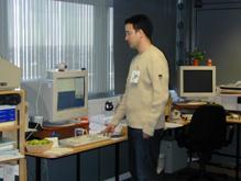
Fig. 15. VNC teleport when user approaches to host.
5. Related Work
SONY’s CyberCode [16] is a visual tagging system based on a 2-D square barcode that alike to TRIP can be used to determine the 3-D position and identifier of tagged objects. The ARToolKit [6] system also chooses a square marker for a similar purpose, however, its identifier encoding capabilities are more limited than in the case of TRIP or CyberCode. Both CyberCode and ARToolKit technologies provide a high degree of location accuracy and work in real-time. They have been mainly applied to the domain of Augmented Reality, in order to correctly register computer-synthesised information on views of the real world. However, these square marker technologies are not as easily identifiable as TRIP circular targets in cluttered environments and therefore are less suitable for the object location and tracking domain we target. Moreover, their marker geometric features require higher image resolution for accurate recognition and location extraction than TRIP.
BBC’s free-d [20] location system measures the precise position and orientation of studio cameras, by using an auxiliary camera mounted on the back of a conventional moving camera pointing to circular markers, similar to TRIPcodes, fixed on the ceiling of a TV recording studio. A hardware implementation of its algorithms is needed to achieve real-time video processing. The system is used for virtual reality TV production, being, in contrast to TRIP, expensive and cumbersome to deploy. Xerox PARC’s Dataglyph [10] is a 2-D barcode technology that uses thousands of tiny, individual 45-degree diagonal lines to encode information. This barcode offers a high density encoding and is robust to partial occlusion. A derivation of Dataglyph, requiring less resolution for its identification, has been used to enhance a conventional notice board with electronic services, alike to the TRIPboard application. Nevertheless, Dataglyph requires far higher resolution for the tag identification and location than TRIP.
6. Further Work and Conclusion
So far, mainly the entity presence identification capability of TRIP has been exploited. Current ongoing work is addressing the creation of sentient applications that make use of the precise 3-D location and orientation information also provided by TRIP. An example application in mind is the use of a TRIPtag as a 3-D mouse for the control of virtual 3-D environments, e.g. in the Quake game. We also hope to deploy, in due time, sufficient number of web-cams across our laboratory in order to make possible the creation with TRIP of a 3-D Location Service covering all our premises.
TRIP is a novel cost-effective and easily deployable sensor technology that offers an excellent degree of accuracy and performance for the identification and 3-D location of tagged entities. This sensor’s off-the-shelf hardware requirements, i.e. inexpensive low-resolution CCD cameras, monochromatic printers to generate its 2-D circular tags and PCs, makes the creation of location-aware reactive environments, even in the home, an affordable proposition. All that is required to augment a standard PC with visual awareness is a standard web-cam which costs less than $50 and TRIP’s software. It is hoped our system will assist in a wider acceptance of the promising Sentient Computing paradigm which provides a more natural and flexible way of interfacing with computers. The set of TRIP-enabled applications presented demonstrates some of the potential of this low-cost but high performing 3-D location system.
Acknowledgements
Diego López de Ipiña would like to
express his gratitude to the Department of Education of the Basque Government
for the sponsorship of his PhD studies. The TRIP project has been sponsored by
AT&T Laboratories,
References
1. Addlesee M, Curwen R, Hodges S, Newman J, Steggles P, Ward A and Hopper A. Implementing a Sentient Computing System. IEEE Computer, August 2001; 34(8): pp. 50-56
2. Brumitt B, Meyers B, Krumm J, Kern A, Shafer S. EasyLiving: Technologies for Intelligent Environments. Handheld and Ubiquitous Computing, September 2000
3. Forsyth D, Mundy JL, Zisserman A, Coelho C, Heller A and Rothwell C. Invariant Descriptors for 3-D Object Recognition and Pose. IEEE Transactions on Pattern Analysis and Machine Intelligence, October 1991; 13(10): 971-991
4.
Harter A, Hopper A, Steggles P, Ward A and Webster P. The
Anatomy of a Context-Aware Application. Proceedings of MOBICOM’99,
5. Hightower J and Borriello G. Location Systems for Ubiquitous Computing. IEEE Computer, August 2001; 34(8): 57-66
6.
Hopper A. Sentient Computing.
The Royal Society Clifford Paterson Lecture. Philosophical Transactions of the
Royal Society
7. Kato H and Billinghurst M. Marker Tracking and HMD Calibration for a Video-based Augmented Reality Conferencing System. Proceedings of the 2nd Internation Workshop on Augmented Reality, October 1999; 85-94
8.
Krumm J, Harris S, Meyers B, Brumitt
B, Hale M and Shafer S. Multi-Camera Multi-Person Tracking for EasyLiving. Proceedings of 3rd International
Conference on Visual Surveillance,
9. López de Ipiña D and Lo S. LocALE: a Location-Aware Lifecycle Environment for Ubiquitous Computing. Proceedings of the 15th International Conference on Information Networking (ICOIN-15) , February 2001; 419-426
10. Moran TP, Saund E, Van Melle W, Gujar AU, Fishkin KP and Harrison BL. Design and technology for Collaborage: collaborative collages of information on physical walls. Proceedings of the 12th annual ACM symposium on User interface software and technology, November 1999
11. Object Management Group. Trading Object Service Specification, May 2000: ftp://ftp.omg.org/pub/docs/ formal/00-06-27.pdf
12. Object Management Group. Notification Service, November 1998: ftp://ftp.omg.org/pub/docs/formal/ 00-06-20.pdf
13. Object Management Group. The Common Object Request Broker Architecture: Architecture and Specification, October 1999: ftp://ftp.omg.org/pub/ docs/formal/01-09-01.pdf
14. OmniORB 3.0 High Performance ORB, AT&T Laboratories Cambridge, 2001: http://www.uk.research .att.com/omniORB/index.html
15. Pilu M, Fitzgibbon A, Fisher R. Ellipse-specific Direct least-square Fitting. IEEE International Conference on Image Processing, September 1996
16. Rekimoto J and Ayatsuka Y. CyberCode: Designing Augmented Reality Environments with Visual Tags. Proceedings of DARE 2000, 2000
17.
18. Stafford-Fraser JQ and Robinson P. BrightBoard: A Video-Augmented Environment. Proceedings of Conference on Human Factors in Computing Systems (CHI96), April 1996
19.
Stillman S, Tanawongsuwan
R and Essa I. A System for Tracking and Recognizing
Multiple People with Multiple Cameras. Proceedings of Second International
Conference on Audio-Vision-based Person Authentication,
20. Thomas GA, Jin J, Niblett T, Urquhart C. A versatile camera position measurement system for virtual reality in TV production. Proceedings of IBC’97, September 1997; pp. 284-289
21. Trucco E and Verri A. Introductory techniques for 3D Computer Vision, Prentice-Hall, Inc, 1998; ISBN-0-13-261108-2
22. Tsai RY. A versatile Camera Calibration Technique for High-Accuracy 3-D Machine Vision Metrology Using Off-the-Shelf TV Cameras and Lenses. IEEE Journal of Robotics and Automation, August 1987; RA-3(4): 323-344. Source code available at: http://www.cs.cmu. edu/afs/cs.cmu.edu/user/rgw/www/TsaiCode.html
23. Want R, Hopper A, Falcão A and Gibbons J. The Active Badge Location System. ACM Transactions on Information Systems, January 1992; 10(1): 91-102
24. Ward A, Jones A and Hopper A. A New Location Technique for the Active Office. IEEE Personal Communications, October 1997; 42-47
25. Weiser M. The Computer for the 21st Century. Scientific American, , September 1992, 265(3):94-104
26. Wellner P. Interacting with paper on the DigitalDesk. Communications of the ACM, August 1993; 36(7): 87-96
27. Werb J and Lanzl C. Designing a positioning system for finding things and people indoors. IEEE Spectrum, September 1998; 71-78